Render Stages Overview
Render stages are ROM-based plug-ins to the Window Server render stage framework. They can be chained to form a rendering pipeline, which takes the draw operations that are produced by the Window Server and ultimately passes them to the UI surface. Render stages can selectively filter, modify, or redirect the draw operation stream, as required—for example, to perform transition effects (TFX).
Variant: ScreenPlay. Target audience: Device creators.
Render stages therefore provide a mechanism for device creators to customize the Window Server rendering pipeline without modifying the Window Server code. In addition, in ScreenPlay the render stages are able to monitor and modify display control attributes, and scale and position the application extent within the full UI area.
Instead of using a concrete rendering API, the Window Server uses abstract APIs, for which the render stage plug-ins provide the concrete implementations.
Architecture
The following diagram shows where render stages fit into the Window Server architecture.

Symbian provides default render stage plug-ins, which are of production quality and reproduce the rendering behavior in Symbian OS v9.4. In ScreenPlay, device creators can replace the render stage plug-ins with their own bespoke plug-ins. In the non-ScreenPlay variant, the interfaces are prototypes and the render stage plug-ins should not be replaced in a real device. Note that different APIs are used in ScreenPlay from the non-ScreenPlay variant. This section documents the ScreenPlay APIs.
Typical use case
The primary use case is that a device creator adds a render stage plug-in into the render stage chain in order to create transition effects (TFX). For example, the device creator could add a TFX engine render stage as shown in the following diagram. This could be used to slide in menus and other elements of the user interface.
The TFX render stage might redirect relevant draw operations onto a TFX surface. Then later the TFX render stage could inject those captured drawing operations into the displayed scene over a sequence of frames, in order to create the desired effect.
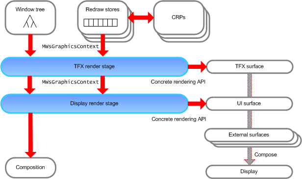
The render stages are stacked on top of each other—effectively they are chained into a pipeline, in which the Window Server "talks" only to the first render stage. This render stage in turn talks only to the second render stage. Notice that the second render stage uses a concrete rendering API to control the UI surface. This is in contrast to the first render stage, which uses the abstract MWsGraphicsContext API, which acts as a proxy for the concrete API.
Let us look at how it works in sequence. Redraw stores hold GDI draw operations and then play them back. The abstract interface for GDI draw operations is MWsGraphicsContext and the redraw stores pass the draw operations on to the first render stage in the chain using MWsGraphicsContext calls. The first render stage in the chain processes these and passes a possibly modified stream of GDI operations on to the second render stage (which is the final render stage in this example). This final render stage converts the GDI operations into concrete rendering calls (such as BitGDI or OpenVG) for rendering into the UI surface. However, alternatives are possible. For example, redraw stores can also include DrawWsGraphic() calls, which when played back result in the execution of Content Rendering Plug-ins (CRPs).
Window Server clients can introduce external surfaces into the scene using RWindowBase::SetBackgroundSurface(). These are tracked through the window tree using the abstract interface for the composition context. The final render stage converts these abstract interface calls into calls to the composition interface.
Note that render stage chains are on a per-screen basis. If there are multiple screens, there are multiple render stage chains. The chains can use the same render stage classes, but they use different object instances of those classes.
Implementing the interfaces
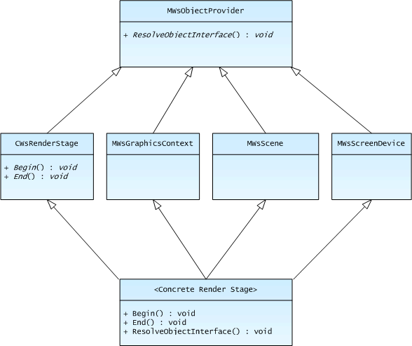
After it constructs the render stage chain, the Window Server requests various interfaces from the top render stage using the Window Server's object provider mechanism. Some of the interfaces are mandatory, some are optional.
Usually each render stage in the chain implements the interfaces and passes the calls through to the next render stage. For example, a TFX render stage might redirect some GDI draw operations and play them back later, so that what passes in at the top is not the same as what passes out at the bottom. In this case, the render stage provides its own implementation of the interface, although that implementation generally calls the implementation provided by the next stage.
However, sometimes a render stage does not need to make any modification to what passes through the interface. Then the render stage does not provide an implementation—it simply passes the draw operations through to the next render stage. For example, generally only the final render stage needs to implement the MWsScreenDevice interface, which provides information about the screen size and orientation.
The following diagram shows a concrete render stage implementing three of the main render stage interfaces. Although this is the usual practice, it is not mandatory. The concrete render stage could instead delegate the implementation of some of the interfaces to helper classes.
Advanced use case
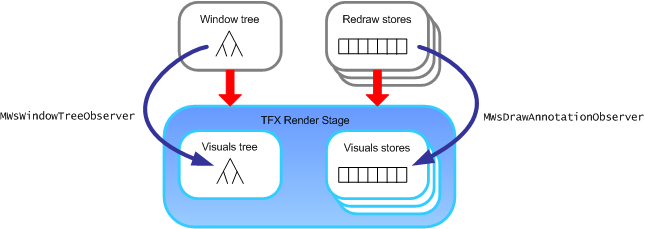
Render stages can optionally create their own visuals tree to mirror the structure of the Window Server's window tree. The render stage can then temporarily change the attributes of nodes in the tree and introduce new nodes that the Window Server does not know about. This enables the render stage chain to introduce sophisticated transition effects.
To create a visuals tree, the render stage must implement the MWsWindowTreeObserver interface. The Window Server uses this to communicate the structure of the window tree to the render stage, so that the render stage can build up its replica tree.
Similarly render stages can optionally capture the drawing for each window from the Window Server redraw stores and build up their own visuals stores to store the drawing for the nodes in the visuals tree. To do this, the render stage must implement the MWsDrawAnnotationObserver. The Window Server uses this to communicate which node in the tree each batch of drawing operations relates to.
Render stages that implement their own visuals stores typically use the Window Server's change-tracking rendering mode. This is an optimization of the Window Server rendering loop for render stages that build visuals stores. The render stage is then responsible for playing back the drawing operations in the visuals store whenever the screen is to be updated. Typically this is done using a painter's-style algorithm.
By implementing a visuals tree and visuals stores, render stages can perform more complex TFX than is possible otherwise. However, implementing a visuals tree and visuals stores is not necessary for some TFX, such as sliding windows onto the screen.
Note: The painter's algorithm (sometimes called priority fill) is a common solution in 3D computer graphics. The algorithm mimics the painting technique of painting the distant parts of a scene before parts that are in the foreground, even though this may result in covering up some of the distant areas. The algorithm sorts the polygons in a scene by their depth and then draws them in order from the back to the front.
Configuring the render stage chain
Parameters in the wsini.ini file control the configuration of the render stages as follows:
The PLUGINS parameter controls which render stages are loaded when the Window Server starts up. In addition, a separate section specifies details (such as ID and type) for each plug-in.
The RENDERSTAGES parameter configures the render stage chain and the CHANGETRACKING parameter selects change-tracking rendering mode (instead of the default dirty-rectangle tracking mode). You can specify these separately for each screen, so that different effects can be used for each screen.
Copyright ©2010 Nokia Corporation and/or its subsidiary(-ies).
All rights
reserved. Unless otherwise stated, these materials are provided under the terms of the Eclipse Public License
v1.0.