Panoramic Stitching Guide
This document introduces you to the panoramic stitching functionality.
Panoramic stitching overview
The panorama image is created by stitching a collection of several separate image into one large image. The panoramic stitching process is done by,
The panoramic stitch can be done eihter interactively by using camera viewfinder, for tracking the camera movements or by stitching pre-captured images together.
Introduction about the panoramic stitching
The CImagePanorama stitches a set of images into a single panorama image. The input to CImagePanorama is a collection of high resolution images together with some guidance on the relative positioning between the images expressed by CPanoramaTransform instances.
For the panorama creation, the most common use is rendering a full size panorama image to the device file system.
The high level steps to use CImagePanorama are shown below:
To construct CImagePanorama, use CImagePanorama::NewL() which loads the image panorama plugin.
To initialise CImagePanorama, use CImagePanorama::InitialiseL().
To correct the lens parameter use TPanoramaLens. You need to correct the lens for panorama stitching quality. The lens parameters are camera specific.
To add images to CImagePanorama, use CImagePanorama::AddFileL(),CImagePanorama::AddBufferL() or CImagePanorama::AddImageL(), providing a hint on relative positioning or translation of the images through CPanoramaTransform. This transform only needs to be approximate.
To make the stitched image available call CImagePanorama::RenderL().
The CImagePanorama instance can then be deleted.
Introduction about the CVFTracker
CVFTracker is used to track viewfinder images to aid in capturing a panorama. The usage of CVFTracker are demonstrated as follows:
The CVFTracker output is used for providing feedback and guidance to you, on how to move the camera while capturing a panorama.
The CVFTracker is used as an aid for the stitching process in the CImagePanorama. The input to the CVFTracker is a rapid flow of raw images from the viewfinder of the camera. The output is the movement of the camera.
The high level steps to use the CVFTracker are shown below:
To create CVFTracker, use the CVFTracker::NewL(). The CVFTracker::NewL() is used to load the CVFTracker plugin.
To initialise CVFTracker, use CVFTracker::InitialiseL().
To reset CVFTracker, use CVFTracker::Reset().
To perform the image registration, use CVFTracker::RegisterImageL().
To destroy the CVFTracker, use CVFTracker::~CVFTracker().
Camera requirements
The camera requirements for the CImagePanorama and CVFTracker are as follows,
The camera must provide low resolution images (in the order of 160 by 120 up to 320 by 240 resolution) as the raw format at a high frame rate to the CVFTracker and high resolution captured images to the CImagePanorama.
For the CVFTracker, it is better to have good frame rate than to have high resolution input images.
The use of large CVFTracker images can cause a lower frame rate on slow devices, and do not give accurate tracking for the view finder.
The optimal size of images is a tradeoff between the panorama quality and the time for rendering the panorama.
How to use Panoramic Stitching
This section contains some code snippets to show, how Panoramic stitching is accessed in several situations.
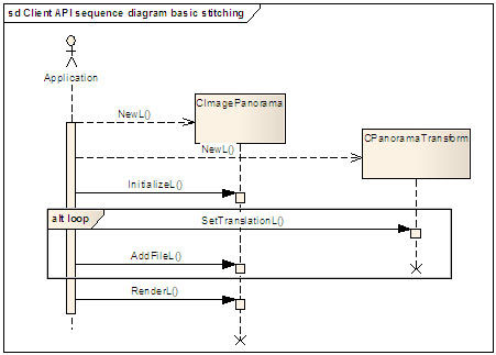
Basic stitching
The basic stitching is demonstrated by a simple example of stitching four JPEG images into a single JPEG image providing an approximate translation between each image:
    TSize imageSize(1200, 1000);

    TDirection direction = EPanoramaDirectionRight;

    //Lens parameters or internal camera characteristics should be available for the
    //specific camera module in use. Here we use default values.
      TPanoramaLens lens;

    //Create transform. A transform is an approximate offset between each image.
      CPanoramaTransform* panTrans = CPanoramaTransform::NewL();
      CleanupStack::PushL(panTrans);

    //Create panorama object.This stitches the individual images together.
      CImagePanorama* panImage = CImagePanorama::NewL();
      CleanupStack::PushL(panImage);

    //Create panorama engine and set the lens and size
      panImage->InitializeL(imageSize, lens, direction);

    //Each file added is provided with an approximate translation.
    //In this case there are 4 images.
      panTrans->SetTranslationL(TPoint(0, 0), imageSize);
      panImage->AddFileL(KTestFileName1, *panTrans);

    panTrans->SetTranslationL(TPoint(900, -30), imageSize);
    panImage->AddFileL(KTestFileName2, *panTrans);

    panTrans->SetTranslationL(TPoint(900, 60), imageSize);
    panImage->AddFileL(KTestFileName3, *panTrans);

    panTrans->SetTranslationL(TPoint(400, -30), imageSize);
    panImage->AddFileL(KTestFileName4, *panTrans);

    //The image size can be obtained before rendering (if required)
      TSize size;
      panImage->CurrentImageSizeL(size);

    //view the output image
      panImage->RenderL(KTestBSOutputFileName);

    CleanupStack::PopAndDestroy(2); //panTrans, panImage
The main steps for using CImagePanorama are as follows,
create CImagePanorama
some approximate transform information for each image pair
add each images to CImagePanorama
render the output (for example to the file)
delete the objects used.
Note: The following points must be noted by you:
The lens parameters are not resolution dependant. It is enough to calibrate once for each camera model and no need to recalibrate for each resolution. For best accuracy, use the highest resolution possible when calibrating with a calibration tool.
The approximate translations in x co-ordinate and y co-ordinate ( as dx, dy) must be compliant with the value of direction.
A camera application example
The CImagePanorama is used in a camera application. The example is more complicated than the previous example. In this example CVFTracker provides the approximate transform between the captured images.
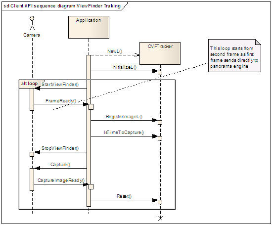
Viewfinder image tracking
The CImagePanorama generates panorama images. The application starts the process and then use the camera for capturing the images. The CVFTracker will give an indication when to capture the high resolution images, which will later be stitched into a panorama image.
The CVFTracker plays an important role for getting the camera movement. The high level steps to use the CVFTracker in the CImagePanorama for a camera application, are shown below:
To create the CVFTracker object and load the CVFTracker plugin, use CVFTracker::NewL().
To create CImagePanorama object and load the CImagePanorama plugin, use CImagePanorama::NewL().
To create the CPanoramaTransform object and set or get the values, use the CPanoramaTransform::NewL().
To create and set the CVFTracker, CImagePanorama, and CPanoramaTransform functions for the Image Processor Adaptation Plug-in objects, use CVFTracker::InitialiseL() and CImagePanorama::InitialiseL() respectively.
To get a translation value from a viewfinder image, register an image by using CVFTracker::RegisterImageL(). This will return translation information as a CPanoramaTransform object.
Check the right time to capture the next image by using CVFTracker::IsTimeToCapture().
Reset the CVFTracker for the next image, using CVFTracker::Reset().
In order to capture many images to be stitched into a single panorama image, repeat the steps 5, 6 and 7.
Panorama stitching
The CVFTracker helps to decide when to capture each of the full resolution images using the camera. The images can then be passed to CImagePanorama and the stitching is done. The high level steps to do panorama stitching are listed below:
Capture the next image using the camera, then add the image to the CImagePanorama by using CImagePanorama::AddImageL() or CImagePanorama::AddFileL, passing in the CPanoramaTransform object obtained from the CVFTracker.
When all images have been captured you can render the stitched image to file, image buffer, CFbsBitmap or image frame using CImagePanorama::RenderL().
User Interface
Provide a good user interface (UI) application for the CImagePanorama is crucial. An example of UI design is described below, which gives you a robust and easy application for generating panorama images.
How to shoot a panorama
The steps to be followed for shooting a panorama images:
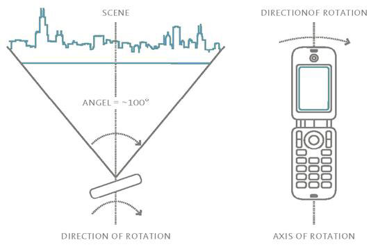
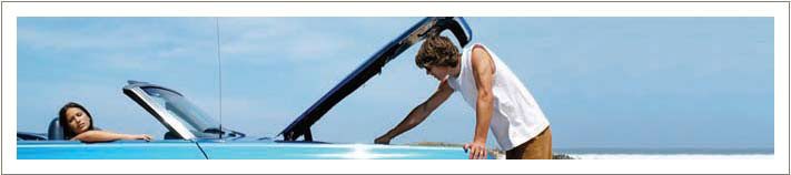
You need to press the start button of the camera and need to sweep the camera towards the wanted scene.
Note: You must try not to move the mobile phone, but only rotate it. You see in the below diagram the camera is sweep in a clockwise direction from left-to-right. The rotation is made around the imagined axis through mobile (axis of rotation in the image). A panorama image covers approximately a 100 degree field of view.
Application Start
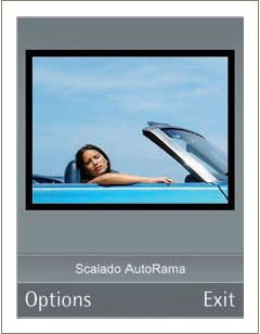
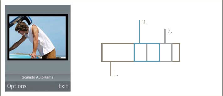
When you launch the application the UI appears as shown in the below diagram.
Here the screen area shows the viewfinder image. When you sweep the mobile, several images are captured and then the images are stitched to create a panorama image.
Capture a panorama image during tracking
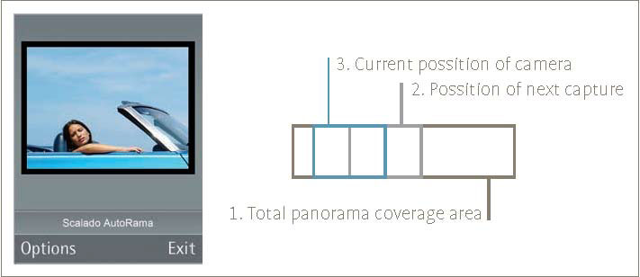
When you choose to capture a panorama image the UI changes, which is shown in the below diagram.
In the above diagram you see three different boxes named 1, 2 and 3 which represent the position of the camera. The blue box representation changes according to the rotation of the mobile phone.
The boxes shown in the above diagram is for illustrative purpose, so that it can be down scaled for viewfinder image size. The total panorama coverage area box is estimated by the number of images for capturing and the overlapping area size.
The code snippets below shows the CVFTracker tracking.
    _LIT(KFileOutput, "c:\\ICLExample\\viewfinder%d.mbm");
    _LIT(KFileCapturedImage, "c:\\ICLExample\\pancapture%d.jpg");
    TInt i = 0;

    TSize imageSize(1200,1000);
 CFbsBitmap* bmp = new (ELeave) CFbsBitmap;
 CleanupStack::PushL(bmp);

    // get 1st viewfinder image from camera into bmp (detail excluded)
             TSize bmpSize = bmp->SizeInPixels();

       CPanoramaTransform* panTrans = CPanoramaTransform::NewL();//create panorama transoform
       CleanupStack::PushL(panTrans);

       CVFTracker* vfTracker = CVFTracker::NewL(); //create VFTracker and load the plugin
       CleanupStack::PushL(vfTracker);

       vfTracker->InitializeL(bmpSize); //Create VFTracker and set size

       CImagePanorama* panImage = CImagePanorama::NewL(); //create CImagePanorama object
       CleanupStack::PushL(panImage);

       TDirection direction = EPanoramaDirectionRight; //assign direction

    // Lens parameters or internal camera characteristics should be available for the
    // specific camera module in use. Here we use default values.
       TPanoramaLens lens;
       panImage->InitializeL(imageSize, lens, direction); //initialise size, lens, direction and create panorama engine

    // get the first captured image from the camera as a starting point - its name is given in capturedFileName
       TFileName capturedFileName;
    capturedFileName.Format(KFileCapturedImage(),i);
       panImage->AddFileL(capturedFileName, *panTrans); //add the captured image

    do
        {
        // give the next camera viewfinder image to the tracker    (details ommitted)
           vfTracker->RegisterImageL(*bmp, *panTrans); // register viewfinder image

        // check if we have a good overlap with the previous image
           if(vfTracker->IsTimeToCapture(direction, KPanoramaDefaultOverlap))
              {
              // capture the next image from the camera (details ommitted)
              capturedFileName.Format(KFileCapturedImage(),i);

                 panImage->AddFileL(capturedFileName, *panTrans); //add the captured image
                 vfTracker->Reset(); //reset the VFTracker object
              }
        if ( err != KErrNone )  // some termination condition usually a signal from user
            {
            // no more viewfinder images
            break;
            }
        }
    while (1);
    panImage->RenderL(KTestVFTOutputFileName); // render the stitched image
    CleanupStack::PopAndDestroy(4,bmp); //panTrans, vfTracker, panImage, bmp
The CVFTracker is passed each viewfinder images which it checks and determines whether it is right time to capture the next image. In return it provides translation information CPanoramaTransform::GetTranslation() which indicates the shift of the current viewfinder image.
The extracted information is used to draw the blue rectangle on the screen. If it is time to capture, then it triggers the capturing function and restarts the CVFTracker again for next image.
Note: The box representation is used in the UI, to help you to take better panorama images. In addition a vibration effect can be used to provide additional feedback on when to capture an image. For example, when you sweep the mobile phone, it is in tracking mode so it vibrates. When the mobile phone is ready to capture, the vibration stops to let you know that it must be static for capturing an accurate second image. Then when it vibrates again, you must rotate the mobile and until it stop.
User interface updating details
The UI design detail is shown in step by step process. They are as follows:
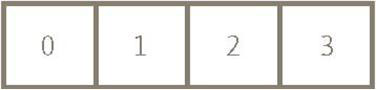
The total panorama coverage area is divided into four different image areas:
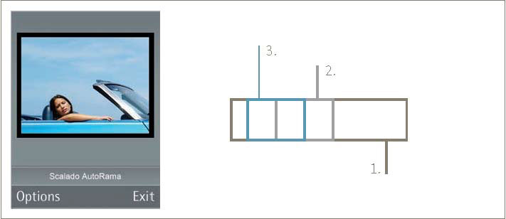
When you choose to capture a panorama image the following steps are performed. The first image is captured at position 0. The UI looks as follows:
When you rotate the mobile phone clockwise, the blue box moves to the right using the translation information from CPanoramaTransform. At the same time the vibrator is set on to give direct feedback for the tracking process. When the blue box and the grey box (which represent the position to capture the next image) coincide, the blue box turns into a filled blue box and the vibrator stops. You then known that the next image is captured. At this moment the camera must be steady.
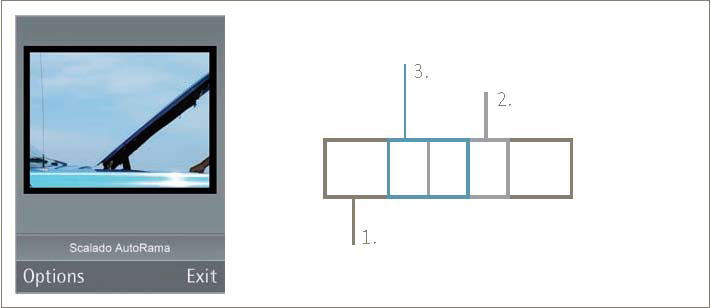
After second image is captured the blue box is moving again and vibrator is set-on. The UI looks as follows:
Again, you rotate the mobile clockwise until the two boxes coincide and vibrator stops; third image then captured. After this, the UI looks as follows:
You rotate the mobile phone until the boxes coincide and the fourth (last) image is captured.
Note: If the mobile phone rotation deviates from chosen (clockwise) direction or translates up and down, the blue box indicates this, and you must correct the mobile phone for the wrong movement.
At this point the stitched image can be saved or you can reset the camera, to create another panorama image:
Camera calibration
In order to produce good panorama images, the internal characteristics of the camera is calibrated by the TPanoramaLens(). The lens parameter such as the distance, the focal length, the principal point, the skew, the width and the height are called the intrinsic parameters.
The camera module supplier should be able to provide this information or there are a number of tools to get the camera parameters. A free tool that can be used is the calibration functions in OpenCV. Typically these tools need an input of images of a special reference pattern, for example a checker board like grid, photographed from many directions. From that the tools automatically generate all the desired lens parameters.
Copyright ©2010 Nokia Corporation and/or its subsidiary(-ies).
All rights
reserved. Unless otherwise stated, these materials are provided under the terms of the Eclipse Public License
v1.0.