Render Stage Display Control and Mapping
ScreenPlay has a new approach to display resolution control to support externally connected displays, such as TV-out. It involves the render stages plus a number of other components in the Graphics package, including the Window Server and the composition engine. The render stages are able to monitor and modify display control attributes, and to scale and position the application extent within the full UI area. In addition, they can optionally implement a display policy, which determines the UI to composition mapping policy.
Variant: ScreenPlay. Target audience: Device creators.
This topic builds on the material covered in the following topics:
Render stage display control and mapping interfaces
The following diagram provides an overview of the render stage display control interfaces. There is further information about the interfaces under separate headings below the diagram.
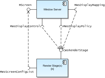
Symbian provides a reference render stage implementation that device creators can use as an example when implementing their own. It demonstrates how to implement these interfaces. See Window Server Plugins Component Overview for more information.
MWsDisplayControl
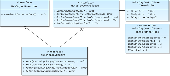
MWsDisplayControl is derived from the MWsObjectProvider and MDisplayControlBase interfaces as shown in the following diagram.
For a diagram of the TDisplayConfiguration class hierarchy, see the Common Graphics Headers Component Overview.
A render stage uses the MWsDisplayControl interface to intercept MDisplayControlBase::GetResolutions() calls at runtime. A render stage can add virtual resolutions into the list of display resolutions in order to scale the full UI area to the full composition area. Using virtual resolutions in this way reduces the memory required for the UI buffers and allows the Window Server to work purely in the application UI coordinate space. Virtual resolutions are marked with a flag in the TResolution structure provided by GetResolutions(). The structure also includes the size of the resolution in both pixels and twips. A render stage may also remove physical resolutions from the list in order to disable the client's ability to change the resolution.
A render stage that provides virtual resolutions can include one (or more) virtual resolutions that give the UI pixel aspect ratio to fit a screen mode defined in the wsini.ini file. However, this may require anisotropic scaling of the UI surface in the composition engine. For example, PAL has 720 x 576 non-square pixels. To get approximately square pixels, virtual resolutions of either 788 x 576 or 720 x 540 would work on a 4:3 display, and 1050 x 576 or 720 x 395 would work on a 16:9 display. The choice of stretching or shrinking virtual resolutions may depend on the quality of scaling available and other factors, and should only be used for backwards compatibility purposes. This is because 1:1 or integer scaling generally gives a better appearance for user interfaces. Providing shrinking virtual resolutions may also raise expectations in applications of a higher horizontal resolution than actually exists.
The term real resolution is used for the display resolutions that are returned by the composition engine adaptation. These correspond to the supported composition spaces that the Window Server can select for output. These may be scaled and filtered beyond the composition engine adaptation (for example, in the physical display device, such as an HDMI TV).
In addition to defining static screen modes in the wsini.ini file, device creators can define one or two dynamic screen modes in the wsini.ini file. These are used to represent the current display configuration—one for 0° and 180° rotations and the other for 90° and 270° rotations. The latter has the dimensions in both pixels and in twips swapped, to appear similar to the static modes. You define a dynamic screen mode by setting the SCR_WIDTH and SCR_HEIGHT parameters to -1. If there is only one dynamic mode, it is not possible to use the CWsScreenDevice API to change the current rotation by 90 degrees.
If MDisplayControl::SetConfiguration() is used to change the configuration, the dynamic mode(s) are updated as necessary. With two dynamic modes, if one is the current mode, the other generally becomes the new mode (even if only the resolution changed, for example) so that applications see a mode number change. The only time this does not happen is in the case of a 180° rotation, because the static mode behavior is to retain the current mode.
Whenever the dynamic mode data changes, or a new mode is selected, an EEventScreenDeviceChanged event is sent to all clients that have enabled it. Window Server client functions are provided to query whether the current or a given mode index is dynamic.
Without dynamic size modes, an application can still use the full display, by positioning windows outside the reported display area.
MWsDisplayMapping
MWsDisplayMapping is an "information" interface, answering questions rather than anything else. In ScreenPlay, there are several coordinate spaces and there is a common requirement to map a rectangle from one space to another. The render stage implements this interface and ultimately the Window Server exposes the mapping feature to its clients. The MWsDisplayMapping interface derives from the MWsObjectProvider and MDisplayMappingBase interfaces as shown in the following diagram.
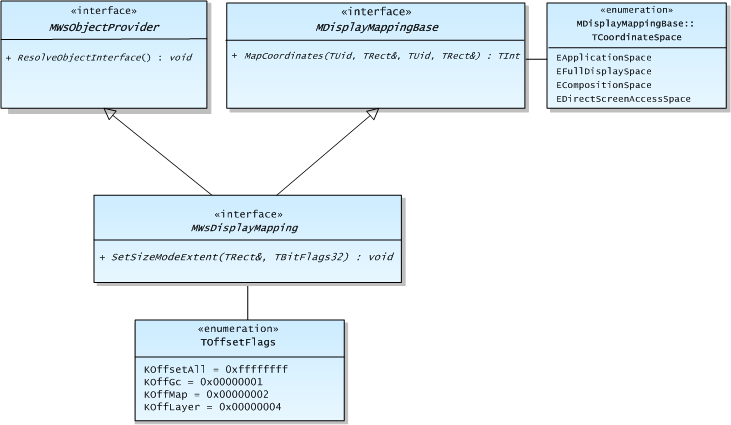
The MWsDisplayMapping interface is very flexible. UIDs are used to signify the application UI coordinate space, the full UI space, the composition/display coordinate space (which may be a different scale to the UI coordinate space) and the Direct Screen Access (DSA) space (which may match the full UI space, or be offset relative to the application UI space).
The MDisplayMappingBase::MapCoordinates() function simply takes a rectangle, a source space and a target space and returns the correspondingly mapped rectangle in the target space. The render stage must guarantee that if two rectangles abut in the source coordinate space, their mapped equivalents also abut. For information about the use of the MapCoordinates() function by Window Server clients, see Display Control and Mapping in the Window Server Client.
The MWsDisplayMapping::SetSizeModeExtent() function sets the screen mode extent for use in one or more contexts. If this is successful, the offset is set on the render stage pipeline in two ways:
Firstly, the offset applies to rendering and must only affect the coordinates in the first render stage that actually performs rendering, and not to later stages. For example, in the reference configuration of the flicker buffer and display render stages, only the flicker buffer render stage applies the rendering offset. A render stage using a CGraphicsContext can use SetOrigin() to apply the offset. Other graphics contexts may have a similar feature.
Secondly, the offset is applied to translate the coordinates of the scene element's destination rectangle (layer extent). This means it is applied only by the first stage that implements the scene element translation. In the reference configuration, this is the display stage.
MWsDisplayPolicy
MWsDisplayPolicy is an optional interface, which derives from MWsObjectProvider as shown in the following diagram. The main purpose of MWsDisplayPolicy is to enable the render stage chain to position the application extent as intelligently as possible to suit the resolution. However, there is no requirement for the render stage chain to implement the interface. If it is not implemented, the offset defined in the wsini.ini file is used. If that is not available a zero offset is used.
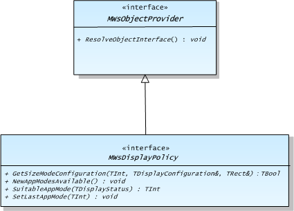
The GetSizeModeConfiguration() function determines the display configuration and application rendering extent to use for a given screen mode defined in the wsini.ini file. The Window Server calls this when an eligible client does one of the following:
Sets the system screen mode using CWsScreenDevice::SetScreenMode(). In this case the configuration structure passed to the policy function is empty because it is the current configuration.
Sets a new display configuration. In this case the requested configuration is passed to the policy function.
On success, the render stage fills in the TDisplayConfiguration structure. Then the Window Server calls the following as appropriate:
MWsDisplayMapping::SetSizeModeExtent() and passes the configuration structure to indicate the position and size of the application area.
MWsDisplayContol::SetConfiguration() and passes the configuration structure to indicate the appropriate real or virtual display resolution.
On failure, the current screen mode and display resolution are retained, but a screen device changed event should still be sent, because there is no way to return failure to the caller.
Applications are given the static offset associated with the screen mode, not the offset described above. Note that because of the way that DSA works, if the render stage uses a CFbsScreenDevice object for rendering, the DSA buffer and the UI buffer are the same (that is, the Screen Driver surface). This means that the offset returned by this policy function must be the same as the one passed in. The policy function has the option to reject the mode change, however.
The Symbian display render stage applies a "best fit" approach, taking into account virtual resolutions if configured, whereby the offset and resolution are chosen to make the screen mode fill as much of the display as possible, while retaining the same (or very similar) pixel aspect ratio. The offset may be limited if the Screen Driver surface is being used for rendering, as described above. The quality of the scaling of screen modes to virtual resolutions and real resolutions is determined by the DP_SCALING wsini.ini file parameter. However, more typically a render stage would implement just one scaling mode, and not require configuration.
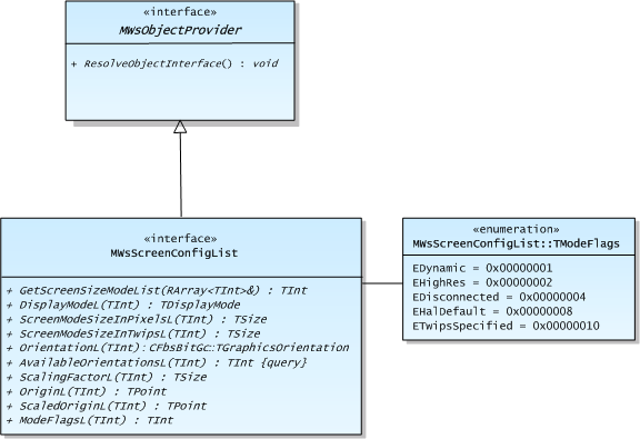
MWsScreenConfigList
The Window Server exposes the MWsScreenConfigList interface for use by render stages. Render stages can use this to get the screen mode parameters for a given index without parsing the wsini.ini file. This interface is similar to MWsScreenConfig, which applies only to the current mode. The MWsScreenConfigList methods leave only if the mode index is out of range.
Copyright ©2010 Nokia Corporation and/or its subsidiary(-ies).
All rights
reserved. Unless otherwise stated, these materials are provided under the terms of the Eclipse Public License
v1.0.